Before we begin if you already know this you can skip to
Studying Elevator entrance in drawings ( detailed )
If you are unfamilier about elevator basics, how elevators works and all you have to first read
Elevator Basics
If you come across any doubt please comment below. This will help us to post your question's solution. And will help you and anyone reading this article.
So back to the subject.....
The elevator drawings are easy to read. They will be a little confusing at the first. But if you once get a hold on it then its fine. To read the elevator drawing, you must know the parts of an elevator. I mean the common parts of an elevator. The elevator have different kinds of drawings.
1. Shaft top view ( shaft plan ).
Some will say hoist-way for the shaft (Click here if you don't know what a shaft is ).
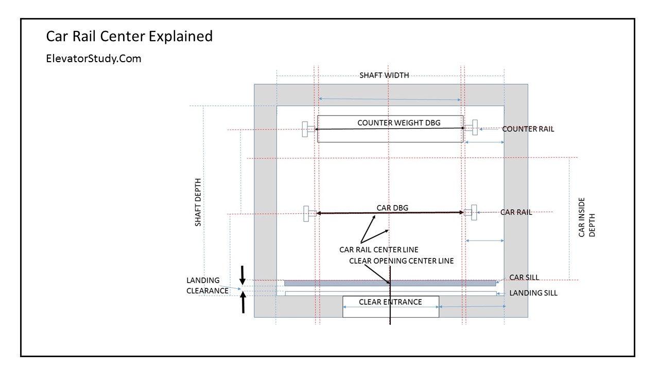
This drawing shows the main bone positions of elevator guide rails, distance between rails, cabin size, shaft size, entrance size, entrance position, running clearance, counter weight position. counter weight size, etc..

The above drawing shows the typical elevator shaft plan. I hope you know about the below terms already
1. Elevator car
2. Rail
3. Sill
4. Entrance
5. Counter weight
6. Shaft / hoist way
If you don't know about the above terms please go to "elevator tree" and select your appropriate level.
Ok. Now all of you reading this should know the above terms. The elevator/lift shaft plan is one of the main drawing that need to be understood thoroughly. This drawing is the top view ( view from the top ).
Now you can see the shaft. The inside dimensions of the shaft is the one we need to take care of. Here you can see the shaft depth and width which are the main dimensions from which we will be deriving another measurements.
Now the actual purpose of the drawing is to give the exact guidance for shaft/ hoist-way construction and elevator/lift installation. The shaft plan is used to make the template for the lift installation. You can always refer the elevator tree in menu bar for knowing more about shaft plan.
Car DBG
The measurement is the distance between two guide rails that guide the elevator cabin , other vise called elevator car or lift car. This is an important measurement because guide rails should be completely perpendicular and parallel without any twist. The DBG ( DISTANCE BETWEEN GUIDE RAILS) must be exactly the value given in the drawing in all along the elevator shaft.
This will determine the quality of the elevator ride in the mechanical manner.
Counter weight DBG
As in the case of CAR DBG this is the displacement between two guide rails which are guiding the counter rails. As in the case of CAR DBG this measurement also will effect the quality of the elevator ride.
Landing clearance / Running clearance
This is the distance between landing sill and car sill. This measurement is universal. it will be always 30mm. Usually this will not be included in the drawing but we have to include this in our calculations. This measurement is so important because this small gap should be maintained all along the lift travel. Passenger safety and door coupling are depending up on it. The huge moving elevator car is moving in this clearance with the stationary lading entrance.
Car rail center line & Entrance center line
 In the drawing you can see there is two car rail center line.
1. Horizontal
2. Vertical
both are important lines.
Entrance center line is also shown in the drawing. The importants of this is in some drawing the vertical car center line and the entrance center line( clear opening center line) may not be aligned. There may be an offset between these two. The offset is a very important measurement need to be considered during the installation. In the below drawing you can see the entrance offset explained.

Studying Elevator entrance in drawings ( detailed )
If you are unfamilier about elevator basics, how elevators works and all you have to first read
Elevator Basics
If you come across any doubt please comment below. This will help us to post your question's solution. And will help you and anyone reading this article.
So back to the subject.....
The elevator drawings are easy to read. They will be a little confusing at the first. But if you once get a hold on it then its fine. To read the elevator drawing, you must know the parts of an elevator. I mean the common parts of an elevator. The elevator have different kinds of drawings.
1. Shaft top view ( shaft plan ).
Some will say hoist-way for the shaft (Click here if you don't know what a shaft is ).
This drawing shows the main bone positions of elevator guide rails, distance between rails, cabin size, shaft size, entrance size, entrance position, running clearance, counter weight position. counter weight size, etc..

The above drawing shows the typical elevator shaft plan. I hope you know about the below terms already
1. Elevator car
2. Rail
3. Sill
4. Entrance
5. Counter weight
6. Shaft / hoist way
If you don't know about the above terms please go to "elevator tree" and select your appropriate level.
Ok. Now all of you reading this should know the above terms. The elevator/lift shaft plan is one of the main drawing that need to be understood thoroughly. This drawing is the top view ( view from the top ).
Now you can see the shaft. The inside dimensions of the shaft is the one we need to take care of. Here you can see the shaft depth and width which are the main dimensions from which we will be deriving another measurements.
Now the actual purpose of the drawing is to give the exact guidance for shaft/ hoist-way construction and elevator/lift installation. The shaft plan is used to make the template for the lift installation. You can always refer the elevator tree in menu bar for knowing more about shaft plan.
Car DBG
The measurement is the distance between two guide rails that guide the elevator cabin , other vise called elevator car or lift car. This is an important measurement because guide rails should be completely perpendicular and parallel without any twist. The DBG ( DISTANCE BETWEEN GUIDE RAILS) must be exactly the value given in the drawing in all along the elevator shaft.
This will determine the quality of the elevator ride in the mechanical manner.
Counter weight DBG
As in the case of CAR DBG this is the displacement between two guide rails which are guiding the counter rails. As in the case of CAR DBG this measurement also will effect the quality of the elevator ride.
Landing clearance / Running clearance
This is the distance between landing sill and car sill. This measurement is universal. it will be always 30mm. Usually this will not be included in the drawing but we have to include this in our calculations. This measurement is so important because this small gap should be maintained all along the lift travel. Passenger safety and door coupling are depending up on it. The huge moving elevator car is moving in this clearance with the stationary lading entrance.
Car rail center line & Entrance center line
1. Horizontal
2. Vertical
both are important lines.
Entrance center line is also shown in the drawing. The importants of this is in some drawing the vertical car center line and the entrance center line( clear opening center line) may not be aligned. There may be an offset between these two. The offset is a very important measurement need to be considered during the installation. In the below drawing you can see the entrance offset explained.


